For a while a question has been hunting me: How the transformers really work under the hoods? Below I present some gathering I got from the internet, including concepts, formulas and some explanation about it. Have fun!
1 - What is a transformer? According to wikipedia:

In other words, the transformer changes the voltage applied to a new value, smaller or greater than the original value. The applied voltage is commonly called the primary voltage or primary winding, and the converted value is called the secondary voltage or secondary winding. NOTICE transformers are by their nature bi-directional, “primary and secondary” concepts are dependent of the way you are going to use it. If you get a transformer 110/220, this can be used to convert 110 (primary) to 220 (secondary), or backwards, 220 (primary) to 110 (secondary).

2 - How does this work? When one alternating current is applied on the primary coil of the transformer this generates a magnetic field due to the inductance. This magnetic field then inducts a current on the secondary coil of the transformer. The relation of the applied and the converted voltages depends on the wire turns in both coils as in the following formula:

3 - Power and current: According to the physics's law the power in the primary and in the secondary must remain the same. As the power of the circuit is voltage multiplied by the current, the current in the secondary coil will be proportional to the current and inversely proportional to the voltage in the primary coil (as bigger is the voltage in the primary, as smaller is the current in the secondary). This relation is best described in the following formula:

Where Vs is voltage in the secondary, Vp is the voltage on the primary, Ip is the current on the primary and Is is the current on the secondary. As an example, if we have 2 amperes in the primary with a voltage of 220 and we want to transform this to 110 volts, the current in the secondary will be 4 amperes, as following:

4 - Defining current and wiring: As mentioned before, the current is related to the wiring used, as bigger the current as thick the wire must be. Before knowing the thickness, we need to calculate how many turns of wire the coil must have. The primary step for these calculations is to define the area of the transformer core. All further calculations are based on this. This is very simple to find and its based on the power in watts the transformer must supply. The area is calculate in square centimeters (cm2).
.gif)

Following our previous examples, lets calculate the area needed for a transformer which has 220V and 2A (440W) on the primary coil.

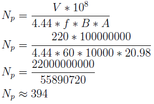
After calculating the area of the core, now is just calculate how many turns of wire we are going to need in the primary coil. This is done using the following formula derived of e.m.f. for AC:

Where Np is the number of turns in the primary, V is the RMS voltage, f is frequency of the alternating current in hertz, B is the magnetic flux of the core material in Gauss and A is the area of the core in cm2. The magnetic flux (in Gauss) of the material is given by the material supplier. When this number is unknown, use 10000 for a approximate calculation. 4.44 is 4 times the alternating current form factor. As the original formula uses m² for A and Tesla for magnetic flux, we need to multiply A by 10⁻⁴ (to convert cm² to m²) and multiply B by 10⁻⁴ (to convert Gauss to Tesla), rearranging the equation we get 10⁸ on its numerator. Continuing with the previous example, let's calculate the number of turns necessary for 220V, 2A, and the frequency of 60Hz.


1 - What is a transformer? According to wikipedia:
“A transformer is a device that transfers electrical energy from one circuit to another through inductively coupled conductors—the transformer's coils.”

2 - How does this work? When one alternating current is applied on the primary coil of the transformer this generates a magnetic field due to the inductance. This magnetic field then inducts a current on the secondary coil of the transformer. The relation of the applied and the converted voltages depends on the wire turns in both coils as in the following formula:
Where Vs is the voltage in the secondary, Vp is the voltage on the primary, Ns is the number of turns in the secondary and Np is the number of turns in the primary. This formula will be used and explained later on this post.
4 - Defining current and wiring: As mentioned before, the current is related to the wiring used, as bigger the current as thick the wire must be. Before knowing the thickness, we need to calculate how many turns of wire the coil must have. The primary step for these calculations is to define the area of the transformer core. All further calculations are based on this. This is very simple to find and its based on the power in watts the transformer must supply. The area is calculate in square centimeters (cm2).
.gif)
Where A is the section area in square centimeters (cm2), W is the power (voltage x current) and Q is a material quality factor. This factor is based on the quality of the material used for the core. Typically this is 0.8 for very good materials, 1 for regular materials and 1.2 for poor materials. As a rule of thumb, use 1 for calculations for homemade transformers. Similarly, one can rearrange this equation to discover the power for a given section area. This would result in W = A² / Q. Some books usually choose 1.1 for Q, resulting the given equation => W = A² / 1.1.
Below we can see an example of what a transformer core looks like. The core is mounted using E plates which can be found in several sizes. During the mount process 2 things must be kept in mind: The area must be as close as possible from the value found in the formula and the core's shape must be as similar as possible from the square shape. The core's area can be calculated from the E plates multiplying its width by its height in centimeters. In the picture below the core's area is shown in blue.

Following our previous examples, lets calculate the area needed for a transformer which has 220V and 2A (440W) on the primary coil.

Now that we know how many turns we need in the primary coil, we just use the formula given above to calculate the number of turns in the second coil for the voltage of 110V, as follows:
The number of turns in the secondary coil is 197. As stated before, for this example, the current in the primary is 2A and the current in the secondary is 4A. The thickness of the wire is defined by these values and can be calculated using the following formula:
Where d is the diameter of the wire in millimeters (mm), I is the current in amperes and J is current density in the material in amperes per square millimeter (A/mm2). The density is a decimal number commonly in the range from 1 to 2. When using 1 the transformer will flow without extra heating but more material are used. When using 2, less material is needed to build the transformer but this cannot be used for long periods because this can literally burn. A widely used value is 1.5. Below is the calculation for the primary and secondary coils for our example.
For our example the wire thickness for the primary coil must have at least 0.85mm and for the second at least 1.7mm. In stores the wires are sold by the AWG table, see below what is the closest greater value for the diameter found in the formula. For our examples, the wire for the primary coil is AWG 19 (0.91mm) and for the secondary coil is AWG 13 (1,83mm).
Related material can be found in:
Very nice and clear. Keep up the good work!!!
ReplyDelete