Monday, October 10, 2011

Bending materials

Have you ever wondered how to calculate the precise amount of weight some materials can handle? Let's suppose you want to build a old fashioned furniture for that audio system of yours using some nice wood you have in home and need to know if the wood will hold the audio weight. This can be achieved using formulas regarding strength of materials, more precisely the bending property.

1. Bending tensile strength (i.e. Yield strength or rupture tensile): The first thing we need in order to continue with our calculations is to discover what is the bending tensile strength of the material we are using. This value represent the edge where the material will break if that amount of pressure is applied to it. These values can be obtained from the suppliers (commercial materials) or a search in the net also can help. These values are not always expressed in the same unity, being the most common units: psi (pound per square inch), Map (mega pascal), N/mm2 (Newton per square millimeter), kgf/cm2 (kilogram-force per square centimeter), etc. None of them are better than other, they are just a way of see the pressure the material can hold. We are going to work with kgf/cm2 as this is one of the most used. If you find the bending tensile strength in some other unity you can use this site to convert it to kgf/cm2.

2. Choosing the material:  The material we are going to use for the tests is the very well known Plexiglas (PMMA), some more info about this material can be obtained here. The Plexiglas tensile strength is around 11000 psi, thus this is about 773.4 kgf/cm2.

3. Defining the shape: Having the first property we can now discover how to calculate the weight some material can handle for a given shape. There are formulas for most of the shapes we can find over the market, for the sake of simplicity we are going to do calculations using the rectangular shape (the most common one). The properties used by the formulas depend on the way the shape is being hold, more precisely which side are supported by a base (foundation pillars). Using the example from the picture below we can clarify this.


From the picture above we have the following variables:

b is the side of the rectangle hold by the foundation pillars.
h is the height of the rectangle.
L is the side of the rectangle from pillar to pillar
P is the force applied over the shape.

As we are working with kgf/cm2 all measurement must be made using centimeters, and P must be calculated using kilogram-force (kgf). Kgf is just the weight of the material in kilograms.

4. Formulas: There are a couple of formulas that we are going to use to calculate the material. Below I present some of the formulas related to the rectangular shape. Notice the shape is formed by the b and h sides, also known as section.


Tr is the bending tensile strength in kgf/cm2.
F is a security factor (see section below).
Tf is the acceptable bending tensile strength calculated based on the security factor.
Mf is the maximum flexure (bending) moment in kgf
P is the force applied to the rectangular shape in kgf.
L1 is the distance from pillar 1 to the point where P is applied (in centimeters).
L2 is the distance from pillar 2 to the point where P is applied (in centimeters).
L is the distance from pillar to pillar.
I is the inertia momentum (no external forces being applied to the material).
y is a imaginary line that divides the height of the shape in 2.
W is the resistance module of the material (in cube centimeters)
b is the side of the shape hold by the pillars (in centimeters).
h is the height of the shape (in centimeters).

5 - Security Factor: This is a number made by certain considerations about the elasticity and discharge of the material and also based on the way (effort) the weight is going to be applied over the shape. The effort for the security factor is divided into 4 groups:


  • Static - The weight is applied over the material statically —this is kept in the same place all the time.
  • Intermittent - The weight is applied and released from the material periodically.
  • Alternate - The weight is applied periodically in both directions (up and down).
  • Abrupt - The weight is released over the material abruptly and periodically.
For each group there is a security factor to be used for certain types of materials. If you don't know which type to use try to find the material that has the closest Tr of the material you are using.


Material/Effort
StaticIntermittentAlternateAbrupt
Cast iron6101520
Soft Iron56812
Hard Iron46812
Wood8101520
Security Factor

6 - Plugging the numbers: Now, suppose we have a piece of Plexiglas with these dimensions: b is 10 cm, L is 20 cm and h is 2 cm. What is the maximum weight in kilos this shape can hold? Remember we already know that the bending tensile strength (Tr) of the Plexiglas is about 773.4 kgf/cm2. Let's discover what is the appropriate flexure tensile (Tf) using the security factor. I'm going to use 8 for the security factor as the bending tensile strength from Plexiglas is very similar to wood and our audio system will sit statically over the shape.


P is going to be applied in the center of the shape (equilibrium point), in this way the weight is going to be distributed among the whole area. Now we are going to need a formula that relates the force applied with the shape we have. In order to do that we are going to need to calculate the resistance module of the material first.

Now we can relate Tf, Mf and W using the following formula:


So we discovered that our piece of Plexiglas can handle 129.204 kgf, or just simplifying, 129 kilograms. Now, it's just a matter of rearrange the formulas in order to solve for any variable you want.

7 - Other Shapes: Below I present some other shapes (section) formulas —if some of the variable is missing this means that the formula is the same as the rectangle shape. if you have trouble finding the one you want, just drop me a message and I can try to find some more information regarding it.


Solid circumference, where d is the diameter.


Tubular circumference, where d is the internal diameter and D is the external diameter.


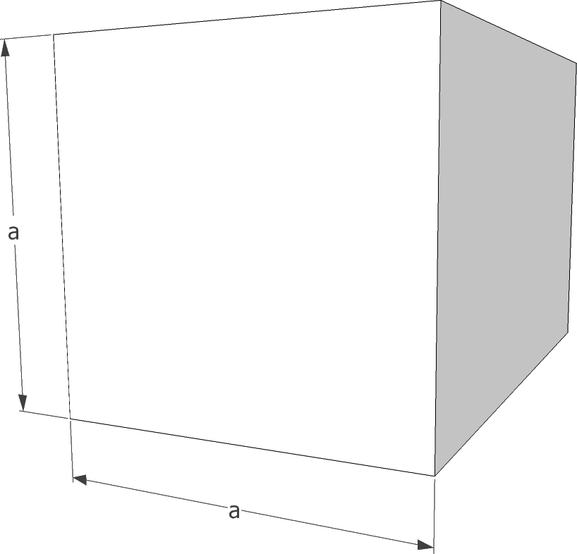
Solid square, where a is the side.


Tubular square, where a is the external side and b is the internal side.


Have fun!

Friday, October 7, 2011

Calling functions dynamically in C

This is not news that someone can loads a function dynamically from a library and use it regularly. But how
about dynamically choosing the function to call and send the number of arguments based on this decision? One can say that this can be achieved using a BIG switch, but, using a switch or ifs we'll always have to change the code when new functions are included, besides that, it will not be fun! :)

This is simpler than it looks, all we have to do is to input some assembler into the code and et-voilà! We just need to pay attention at the calling convention being used. In the _cdecl calling convention the caller must cleanup the stack and as opposite of that, the _stdcall calling convention, the callee (the target function) will do the job automatically. For more details on calling conventions see this article in Wikipedia.

See below the example for the x86 processor in Windows 32 bits assembler. Notice 64 bits numbers are sent in 2 registers, the most significant byte are pushed first on the stack.


#include <stdio.h>

/**
 * This function will be called dynamically (This will return my IQ coefficient! :-)
 */
__int64 _cdecl test_stack(int first,int second,char *third,__int64 last)
{
    return(180);
}

/**
* example on how to execute a function with dynamic arguments passing
* (example valid for x86 in Windows 32 bits for _stdcall and _cdecl calling conventions)
* see http://en.wikipedia.org/wiki/X86_calling_conventions for more detais
*/
int main(int argc,char *argv[])
{
#define MSB_LL(ll) ((long) (ll >> 32))
#define LSB_LL(ll) ((long) ll)
    int            result,first=4,sec=5;char *third="6";
    void          *f=test_stack;
    __int64    ll=123;
    long          hi=MSB_LL(ll);
    long          lo=LSB_LL(ll);

    /* caller must know the type (and order) of the arguments before calling the function */
    _asm {
        push hi        /* last argument is __int64 - push most significant part first */
        push lo        /* now send the least significant part of int64 */
        push third    /* third argument in the function prototype */
        push sec       /* second argument */
        push first     /* first argument */
        call f             /* call function */
#ifdef _STDCALL_CONVENTION
        /* on _stdcall callee must cleanup the stack */
#else
        /* on _cdecl caller must cleanup the stack */
        add esp, 20    /* Stack cleaning  --> add esp, sizeof(long) * arguments */
#endif
        mov hi,edx     /* get result of hi order (only used for 64 bits returns) */
        mov lo,eax     /* get result of low order or integer response */
    }
    ll=((__int64) hi << 32 | lo);
    return(result);
}


Now, suppose that you receive the function pointer as a parameter and you also receive the arguments to be sent to the function in a va_list fashion? Powerful, don't you think?

Have fun!

Thursday, September 22, 2011

What I know about gears, RPM and speed

I was always curious about cars maximum speed, not the one shown in the speedometer, but the real one. So, after some research, this came up to me that the speed is related to 3 simple things.

- RPM: The speed the engine can turn itself in revolutions per minute.
- The gears ratio: How the engine speed can be transferred to tires
- The tires's size: Yes, size matters!

So, lets do the magic.

1 - Gears: The gear is a toothed wheel that when coupled to another gear can alter the relation between the speed of a driving mechanism. This relation about teeth and speed, can be expressed in the following formula:

Where:
  V1 is the speed at the first gear.
  V2 is the speed at the second gear.
  G1 is the number of teeth in the first gear.
  G2 is the number of teeth in the second gear.

Looking at the example below we can see another gears property. Coupled gears work in inverse rotational directions, when gear A is turning clockwise, gear B is turning counter clockwise. If the same rotational direction is needed another gear can be added to the mechanism or pulleys can be used instead.


Using the same example, we can determine what will be the speed at both gears if one of them starts turning. Notice gear A has 12 teeth and gear B has 18 teeth. Applying the formula given above, let's suppose that gear A suddenly starts turning at the speed of 30 RPM, then:


A small gear coupled to a bigger one will decrease the speed of its counterpart (and increase the power of it), which brings us to the following question: What if the gear B was the one that started turning at 30 RPM? So, lets see what happens:

When this speed is applied to gear B, the gear A will start turning at 45 RPM. Therefore, a bigger gear coupled to a small one will increase the speed of the mechanism. Two important things: Gears in the same axis have the same RPM no matters the size of them. When the speed is increased, the power is decreased and vice-versa.

2 - Ratio: Another way of calculate the speed in each gear is use the ratio between the first and second gear. As you will discover, all the car gears are expressed using this number. This can be easily done applying this formula:


Where:
  R is the gear ratio
  G1 is the number of teeth in gear A
  G2 is the number of teeth in gear B
  V1 is speed at gear A (in RPM)
  V2 is speed at gear B (in RPM)

3 - Tires. There is a very good article about tire codes at Wikipedia. I got the picture below from there which I will use to do a little summary about the parts that is related to our job.


From the picture above we are interested in 3 things:


a - Nominal width: This is the width of the tire in millimeters, using the example above the tire's width is 215mm.

b - Ratio of the height to width: The height of the tire is a percentage from its width. Using the example above, this will be 65% of the width: 0.65 x 215 = 139.75mm.

c - Rim diameter code: This is the diameter of the wheel, this is expressed in inches. As all the calculations are done using the metric system, we are going to convert it to meters. Again using the example, the wheel diameter is 15 inches, or 381 millimeters.

We are going to use all these number to discover one simple thing, the circumference of the whole wheel (wheel + tire). From the picture above we can clearly see that the mounted wheel diameter is the wheel size + 2 times the tire height. So, the full diameter will be 381 + 2 * 139.75 = 660.5 mm. Now we just multiply by π and we get the circumference: 660.5 mm * 3.1416 = 2075.03 mm, or approximately 2.07 meters.

3 - Remembering: Let's make a summary about we got until now:

a - We know the engine speed is measured in RPM (a common RPM speed for cruise cars is about 5000).

b - We know that car have gears and these gears have ratios, some of them increase the speed of the engine and some of them decrease it. Some of them are fixed gears (called differentials) and some of them can be changed while you are driving. This is done using the clutch on manual cars, and they are automatically changed on automatic cars.

c - We know that gears on the same axis will turn at the same speed, doesn't matter their sizes.

4 - Speed:  How about after all the gearing the very last gear is attached in the same axis with the wheel? It will just be a matter of calculate all the speed transmission among the gears to discover the RPM at the last gear and as the last gear is in the same axis with the wheel, every time the gear turns, the whole will turns as well, or, every time the last gear turns, the car moves 2.07 meters using the tires from our example (I told you size matters!). Supposing that after all the coupling the last gear is turning at the speed of 10 RPM, the car will be moving at 20.7 meters per minute, or 3.45 meters per second or 12.42 km/h or 7.72 mph.

5 - Common ratios: After a little research in the net I found some gear ratios regarding commercial bikes (B), cars (C) and SUVs (S). See below the table.


VehicleRPM Start Differential Final Differential
Gear ratio
1st2nd3rd4th5th6th
(C) Volkswagen Golf57503.0871.003.362.09 1.471.191.150.98
Speed (km/h) with default tire: 1.81m60.1697.31137.60169.96175.93206.45
(B) Suzuki GSX-R 1000108001.5532.472.687 2.0521.6811.451.3041.208
Speed (km/h) with default tire: 2.00m125.76164.64201233.04259.08279.72
(S) Ranger 3.0 Electronic38003.541.004.082.291.471.000.72-
Speed (km/h) with default tire: 2.19m34.5661.6395.92140.99195.92-
(B) BMW F650 GS Dakar65001.9462.93752.751.751.311.050.88-
Speed (km/h) with default tire: 2.18m54.0288.94118.77148.33176.84-
(B) BMW K 1200 S102501.5592.822.521.841.451.281.141.01
Speed (km/h) with default tire: 1.94m107.67147.48187.17211.96238.04268.65

To calculate the maximum hypothetical speed at any gear just do the math. For instance, to calculate the VW Golf speed at the 3rd gear with default tires:


The ratio is including fixed gears in its calculation (differentials), we just need to multiply them together. Notice these values are expressed as maximum possible values and will rarely be obtained due to external factors, like friction and engine efficiency, which can literally blow if this is kept on the maximum RPM for long periods.

Have fun!

Tuesday, September 20, 2011

Little study about transformers

For a while a question has been hunting me: How the transformers really work under the hoods? Below I present some gathering I got from the internet, including concepts, formulas and some explanation about it. Have fun!

1 - What is a transformer? According to wikipedia:
“A transformer is a device that transfers electrical energy from one circuit to another through inductively coupled conductors—the transformer's coils.”


In other words, the transformer changes the voltage applied to a new value, smaller or greater than the original value. The applied voltage is commonly called the primary voltage or primary winding, and the converted value is called the secondary voltage or secondary winding. NOTICE transformers are by their nature bi-directional, “primary and secondary” concepts are dependent of the way you are going to use it. If you get a transformer 110/220, this can be used to convert 110 (primary) to 220 (secondary), or backwards, 220 (primary) to 110 (secondary).


2 - How does this work? When one alternating current is applied on the primary coil of the transformer this generates a magnetic field due to the inductance. This magnetic field then inducts a current on the secondary coil of the transformer. The relation of the applied and the converted voltages depends on the wire turns in both coils as in the following formula:

Where Vs is the voltage in the secondary, Vp is the voltage on the primary, Ns is the number of turns in the secondary and Np is the number of turns in the primary. This formula will be used and explained later on this post.


3 - Power and current: According to the physics's law the power in the primary and in the secondary must remain the same. As the power of the circuit is voltage multiplied by the current, the current in the secondary coil will be proportional to the current and inversely proportional to the voltage in the primary coil (as bigger is the voltage in the primary, as smaller is the current in the secondary). This relation is best described in the following formula:


Where Vs is voltage in the secondary, Vp is the voltage on the primary, Ip is the current on the primary and Is is the current on the secondary. As an example, if we have 2 amperes in the primary with a voltage of 220 and we want to transform this to 110 volts, the current in the secondary will be 4 amperes, as following:


4 - Defining current and wiring: As mentioned before, the current is related to the wiring used, as bigger the current as thick the wire must be. Before knowing the thickness, we need to calculate how many turns of wire the coil must have. The primary step for these calculations is to define the area of the transformer core. All further calculations are based on this. This is very simple to find and its based on the power in watts the transformer must supply. The area is calculate in square centimeters (cm2).


Where A is the section area in square centimeters (cm2), W is the power (voltage x current) and Q is a material quality factor. This factor is based on the quality of the material used for the core. Typically this is 0.8 for very good materials, 1 for regular materials and 1.2 for poor materials. As a rule of thumb, use 1 for calculations for homemade transformers. Similarly, one can rearrange this equation to discover the power for a given section area. This would result in W = A² / Q. Some books usually choose 1.1 for Q, resulting the given equation => W = A² / 1.1.

Below we can see an example of what a transformer core looks like. The core is mounted using E plates which can be found in several sizes. During the mount process 2 things must be kept in mind: The area must be as close as possible from the value found in the formula and the core's shape must be as similar as possible from the square shape. The core's area can be calculated from the E plates multiplying its width by its height in centimeters. In the picture below the core's area is shown in blue.


Following our previous examples, lets calculate the area needed for a transformer which has 220V and 2A (440W) on the primary coil.


After calculating the area of the core, now is just calculate how many turns of wire we are going to need in the primary coil. This is done using the following formula derived of e.m.f. for AC:


Where Np is the number of turns in the primary, V is the RMS voltage, f is frequency of the alternating current in hertz, B is the magnetic flux of the core material in Gauss and A is the area of the core in cm2. The magnetic flux (in Gauss) of the material is given by the material supplier. When this number is unknown, use 10000 for a approximate calculation. 4.44 is 4 times the alternating current form factor. As the original formula uses m² for A and Tesla for magnetic flux, we need to multiply A by 10⁻⁴ (to convert cm² to m²) and multiply by 10⁻⁴ (to convert Gauss to Tesla), rearranging the equation we get 10⁸ on its numerator. Continuing with the previous example, let's calculate the number of turns necessary for 220V, 2A, and the frequency of 60Hz.


Now that we know how many turns we need in the primary coil, we just use the formula given above to calculate the number of turns in the second coil for the voltage of 110V, as follows:


The number of turns in the secondary coil is 197. As stated before, for this example, the current in the primary is 2A and the current in the secondary is 4A. The thickness of the wire is defined by these values and can be calculated using the following formula:


Where d is the diameter of the wire in millimeters (mm), I is the current in amperes and J is current density in the material in amperes per square millimeter (A/mm2). The density is a decimal number commonly in the range from 1 to 2. When using 1 the transformer will flow without extra heating but more material are used. When using 2, less material is needed to build the transformer but this cannot be used for long periods because this can literally burn. A widely used value is 1.5. Below is the calculation for the primary and secondary coils for our example.


For our example the wire thickness for the primary coil must have at least 0.85mm and for the second at least 1.7mm. In stores the wires are sold by the AWG table, see below what is the closest greater value for the diameter found in the formula. For our examples, the wire for the primary coil is AWG 19 (0.91mm) and for the secondary coil is AWG 13 (1,83mm).


Related material can be found in: